 close
- Productschevron_right
- Learningchevron_right
- Manufacturing solutionschevron_right
- Supportchevron_right


CoroBore® BR30
Three-edge rough boring tools for maximum productivity
Instructions


Diameter adjustment
If no available pre-setter, adjust diameter by measuring the distance from pin to insert and subtract half the pin diameter. Multiply by two for the effective boring diameter.

Torque
Always use a torque wrench and apply recommended torque on screws for insert and tool assembly torque.

Laser-marked scale
The laser-marked scale on the adaptor facilitates setting of the diameter.


Application tips
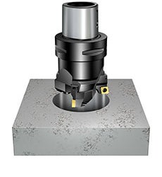
Off-centre holes
If the centre lines of the pre-machined hole and the boring tool are not concentric, the cutting depth could be very large on one side of the hole.
A good solution for these applications is step boring in order to be able to take the large depth of cut. Unsymmetrical cutting forces might bend the tool and cause some small remaining off centre or vibrations, especially when long overhang tool assemblies are used.
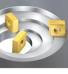
Sand inclusions
Sand inclusions in cast components increase the wear on the inserts.
Recommendations:
• Choose a tough grade
• Reduce cutting data
• Choose a strong square negative basic-shaped insert for improved process security and minimized wear.
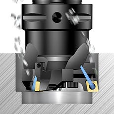
Blind hole
When machining a blind hole it is very important to secure that proper chip evacuation takes place.
Correct cutting data is essential to achieve proper chip forming
Check that the chips do not jam or wear the inserts
Coolant pressure and flow should be sufficient to evacuate the chips
Vertical machines are more critical than horizontal machines for efficient chip evacuation
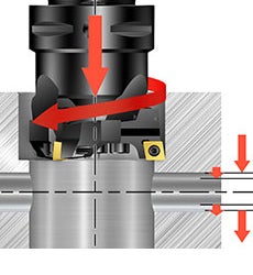
Interrupted cuts
Machining of interrupted cuts, such as cross holes, set high demands on insert cutting conditions.
Choose a tough grade
Choose a strong, square negative basic-shaped insert for improved process security, valid for stable conditions
Reduce cutting data if there are severe interruptions
Recommendations
Cutting data
General recommendations rough boring:
- Starting data: vc 200 m/min (valid when vc on insert box is bigger than vc 200 m/min) at short overhang. Check insert box for feed and depth of cut recommendations
- vc = 50% of recommended data on label. If vibrations occur, reduce speed and increase feed. Do not use max recommended feed and ap at the same time
Machine limitations:
Always make sure the machine can provide the required torque and power for the specific boring application.
Cutting data: CoroBore® 111
| Order code | Grade | Feed range (fn) | Depth of cut (ap) | Cutting speed (vc) | ||||||
| Min | Max | Recommended | Min | Max | Recommended | Min | Max | Recommended | ||
| SPMT0606-BR | 4325 | 0.10 | 0.25 | 0.20 | 0.6 | 4.5 | 2.0 | 365 | 460 | 395 |
| SPMT0606-BM | 2025 | 0.10 | 0.15 | 0.10 | 0.6 | 4.5 | 1.8 | 260 | 265 | 265 |
| SPMT0606-BR | 3210 | 0.15 | 0.30 | 0.25 | 0.6 | 4.5 | 2.0 | 285 | 330 | 300 |
| SPMT0606-BM | 1145 | 0.10 | 0.15 | 0.10 | 0.6 | 4.5 | 1.8 | 15 | 20 | 20 |
| SPMT0808-BR | 4325 | 0.15 | 0.35 | 0.20 | 0.8 | 6.5 | 2.5 | 325 | 425 | 395 |
| SPMT0808-BM | 2025 | 0.10 | 0.25 | 0.20 | 0.8 | 6.5 | 2.2 | 225 | 265 | 240 |
| SPMT0808-BR | 3210 | 0.20 | 0.50 | 0.30 | 0.8 | 6.5 | 2.5 | 235 | 315 | 285 |
| SPMT0808-BM | 1145 | 0.10 | 0.15 | 0.10 | 0.8 | 6.5 | 2.2 | 15 | 20 | 20 |
| SPMT1212-BR | 4325 | 0.15 | 0.40 | 0.25 | 1.2 | 9.0 | 3.0 | 305 | 425 | 365 |
| SPMT1210-BM | 2025 | 0.10 | 0.30 | 0.20 | 1.0 | 9.0 | 2.5 | 205 | 265 | 240 |
| SPMT1212-BR | 3210 | 0.20 | 0.50 | 0.30 | 1.2 | 9.0 | 3.0 | 235 | 315 | 285 |
| SPMT1210-BM | 1145 | 0.10 | 0.20 | 0.15 | 1.0 | 9.0 | 2.5 | 10 | 20 | 15 |
| SPMT1812-BR | 4325 | 0.20 | 0.40 | 0.30 | 1.2 | 1.0 | 3.8 | 305 | 395 | 345 |
| SPMT1810-BM | 2025 | 0.20 | 0.30 | 0.25 | 1.0 | 12.0 | 3.0 | 205 | 240 | 225 |
| SPMT1812-BR | 3210 | 0.25 | 0.50 | 0.30 | 1.2 | 12.0 | 3.8 | 235 | 300 | 285 |
| SPMT1810-BM | 1145 | 0.10 | 0.20 | 0.15 | 1.0 | 12.0 | 3.0 | 10 | 20 | 15 |
Tightening torque
Insert screw
| ISO | ANSI | Non ISO | Code | Size | Torx Plus | Nm | Ft/lbs |
| CC06 | CC2(1.5) | 5513 020-03 | M2,5 | 7IP | 0.9 | 0.7 | |
| CC09 | CC09 | 5513 020-09 | M3,5 | 15IP | 3.0 | 2.2 | |
| CC12 | CC43 | 5513 020-17 | M4x0,5 | 15IP | 3.0 | 2.2 | |
| SP06 | 5513 020-33 | M2,2 | 7IP | 0.8 | 0.59 | ||
| SP08 | 5513 020-57 | M3 | 9IP | 1.7 | 1.25 | ||
| SP12 | 416.1-833 | M3,5 | 10IP | 2 | 1.48 | ||
| SP18 | 5513 020-25 | M4 | 15IP | 3 | 2.2 | ||
| SN15 | SN54 | 5512 086-03 | M6 | 20IP | 6.4 | 4.7 | |
CoroBore® BR30
| | Insert 90° | Insert 84° | |||||||||||
| Size | DCN (mm) | DCX (mm) | ISO | ANSI | Nm | Ft/lbs | Screw size | ISO | ANSI | Non-ISO | Nm | Ft/lbs | Screw size |
| A | 35 | 40.5 | CC06 | CC2(1.5) | 4.8 | 3.5 | M 4 | SP06 | 4.8 | 3.5 | M 4 | ||
| 39.5 | 45 | CC06 | CC2(1.5) | 4.8 | 3.5 | M 4 | SP06 | 4.8 | 3.5 | M 4 | |||
| B | 44 | 50.5 | CC06 | CC2(1.5) | 9 | 6.6 | M 4 | SP06 | 9 | 6.6 | M 4 | ||
| 49.5 | 56 | CC06; CC09 | CC2(1.5); CC3(2.5) | 9 | 6.6 | M 5 | SP08 | 9 | 6.6 | M 5 | |||
| C | 55 | 63 | CC09 | CC3(2.5) | 16 | 11.8 | M 6 | SP08 | 16 | 11.8 | M 6 | ||
| 62 | 70 | CC09; CC12 | CC3(2.5); CC43 | 16 | 11.8 | M 6 | SP12 | 16 | 11.8 | M 6 | |||
| D | 69 | 78.5 | CC12 | CC43 | 16 | 11.8 | M 6 | SP12 | 16 | 11.8 | M 6 | ||
| 77.5 | 87 | CC12 | CC43 | 16 | 11.8 | M 6 | SP12 | 16 | 11.8 | M 6 | |||
| E | 86 | 97 | CC12 | CC43 | 38 | 28 | M 8 | SP12 | 38 | 28 | M 8 | ||
| 96 | 107 | CC12 | CC43 | 38 | 28 | M 8 | SP12 | 38 | 28 | M 8 | |||
| F | 106 | 122 | CC12; CN12 | CC43 | 75 | 55.3 | M 10 | SN12 | SN43 | SP13 | 75 | 55.3 | M 10 |
| 121 | 137 | CC12; CN12 | CC43 | 75 | 55.3 | M 10 | SN13 | SN44 | SP14 | 75 | 55.3 | M 10 | |
| G | 136 | 152 | CC12; CN12 | CC43 | 75 | 55.3 | M 10 | SN14 | SN45 | SP15 | 75 | 55.3 | M 10 |
| 151 | 167 | CC12; CN12 | CC43 | 75 | 55.3 | M 10 | SN15 | SN46 | SP16 | 75 | 55.3 | M 10 | |
| H | 167 | 191 | CC12; CN16 | CC43; CN54 | 75.0; 120,0 | 55.3; 88.5 | M 10; M 12 | SN15 | SN54 | SP17 | 75.0; 120,0 | 55.3; 88.5 | M 10; M 12 |
| 189 | 214 | CC12; CN16 | CC43; CN54 | 75.0; 120,0 | 55.3; 88.5 | M 10; M 12 | SN16 | SN55 | SP18 | 75.0; 120,0 | 55.3; 88.5 | M 10; M 12 | |
Tool holding
Bending stiffness and torque transmissions are the most important factors when choosing a tool holder for boring operations. First choice should always be tools with Coromant Capto coupling, which offers excellent repeatability and the best stability characteristics on the market.
Create account chevron_right
Place orders, view prices and check tool availability
Subscribe to our newsletter chevron_right
Join us. Stay updated.

Sandvik Coromant UK
+44 (0)121 368 0305AB Sandvik Coromant, 811 81 Sandviken, Sweden