 close
- Productschevron_right
- Learningchevron_right
- Manufacturing solutionschevron_right
- Supportchevron_right


CoroMill® 331
Multi-purpose side and face milling cutter

Settings
How to set the width on a full side and face milling cutter.

Working with large corner radius inserts
- When adjusting cutter width (CW) within its lower setting range, the shape of the groove may receive a small notch at the intersection between the radius and the bottom
- Tailor Made inserts with chamfer clearance are available to minimize the overlap and hence reduce vibration

Working with round inserts
For grooves deeper than IC/2, a 0.5 mm (0.020 inch) adjustment of each cassette is recommended
- Widens groove 0.5 mm (0.020 inch)
- Reduces contact length for each insert to 90˚
- Produces a more favorable chip formation and evacuation
- Reduces vibration and power consumption


Application tips
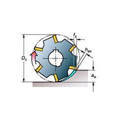
Maximum chip thickness
For parting and grooving milling applications, the most important factor to keep in mind is the maximum chip thickness (hex).
• The engagement to cutter diameter ratio is always less than 30%
• Use optimum hex considering the ae/DC ratio in order to not operate at a too low chip thickness zone, rubbing the work piece instead of shearing
• Right hex value will ensure good cutting action with better surface quality and tool life
Grade selection
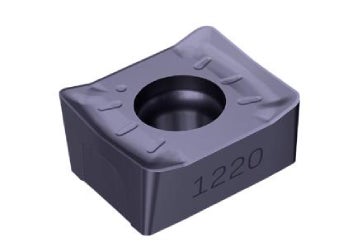
• Use PVD grades as first choice for grooving applications
• Use CVD grades as first choice for half side milling applications
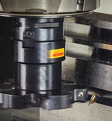
Side and face milling checklist
Make the most out of your slot milling operations by applying these useful hints.
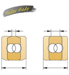
Reduce overlapping problems
• Use Tailor Made inserts with reduced cutting edge length
• Reduces wear in the overlapping zone
• Better chip control and reduced power consumption by up to 10%
Recommendations
Cutter body selection
- The cutters are designed and named after their application area, for example full side & face, half side & face, back face.
- For a required ar, use smallest cutter diameter for best stability
- For a fixed diameter, use cutter with high zn for higher productivity
Full side & face cutter
| Right-hand cutter | |
| Right-hand cassette |

|
| Left-hand cassette | |
Half side & face cutter
| Spindle rotation R | Spindle rotation L | ||
| R style cutter R331.52…R R Cassette |

|
L style cutter L331.52…L L Cassette |
|
| R style cutter R331.52…L L Cassette |
L style cutter L331.52…R R Cassette |
||
| R style cutter R331.52 |
L style cutter L331.52 |
||
| L style cutter L331.52 |
R style cutter R331.52 |
||
Cutting edge length
Smallest cutter width is always recommended when selecting full side and face milling cutter for grooving. Optimizing the overlap of two inserts is critical for stable machining.

Choice of cassette

Half side and face mill

Full side and face mill

Note: The cutter diameter, DC, will be 3.2 mm (0.126 inch) larger with the 8 edge square insert.
| If using larger corner radiis, RE > 1.55 mm | |||||||||
|---|---|---|---|---|---|---|---|---|---|
| Cutter body | Insert radius | 1.55 – 2.60 | 2.61 – 3.50 | 3.51 – 4.50 | |||||
| Cutting width (CW), mm | Insert size | *RC | *LC | *RC | *LC | *RC | *LC | ||
| CM | 6.0 – 8.0 | 04 | 5321-240-15.11 | 5321-240-16.11 | - | - | - | - | |
| DM | 8.0 – 10.0 | 05 | 5321-240-13.11 | 5321-240-14.11 | 5321-240-13.22 | 5321-240-14.22 | - | - | |
| EM | 10.0 – 12.0 | 08 | 5321-240-02.11 | 5321-240-02.31 | 5321-240-02.22 | 5321-240-02.22 | 5321-240-02.33 | 5321-240-02.33 | |
| FM | 12.0 – 15.0 | 08 | 5321-240-03.11 | 5321-240-04.11 | 5321-240-03.22 | 5321-240-04.22 | 5321-240-03.33 | 5321-240-04.33 | |
| KM | 15.0 – 17.5 | 11 | 5321-240-07.11 | 5321-240-08.11 | 5321-240-07.22 | 5321-240-08.22 | 5321-240-07.33 | 5321-240-08.33 | |
| LM | 17.5 – 20.5 | 11 | 5321-240-07.11 | 5321-240-08.11 | 5321-240-07.22 | 5321-240-08.22 | 5321-240-07.33 | 5321-240-08.33 | |
| QM | 20.5 – 23.5 | 14 | 5321-240-09.11 | 5321-240-10.11 | 5321-240-09.22 | 5321-240-10.22 | 5321-240-09.33 | 5321-240-10.33 | |
| RM | 23.5 – 26.5 | 14 | 5321-240-09.11 | 5321-240-10.11 | 5321-240-09.22 | 5321-240-10.22 | 5321-240-09.33 | 5321-240-10.33 | |
| Cutter body radius modification | 2.0 | 3.0 | |||||||
| Cutter body | Insert radius | 4.51 – 5.50 | 5.51 – 6.50 | ||||
|---|---|---|---|---|---|---|---|
| Cutting width (CW), mm | Insert size | *RC | *LC | *RC | *LC | ||
| KM | 15.0 – 17.5 | 11 | 5321-240-07.44 | 5321-240-08.44 | 5321-240-07.55 | 5321-240-08.55 | |
| LM | 17.5 – 20.5 | 11 | 5321-240-07.44 | 5321-240-08.44 | 5321-240-07.55 | 5321-240-08.55 | |
| QM | 20.5 – 23.5 | 14 | 5321-240-09.44 | 5321-240-10.44 | 5321-240-09.55 | 5321-240-10.55 | |
| RM | 23.5 – 26.5 | 14 | 5321-240-09.44 | 5321-240-10.44 | 5321-240-09.55 | 5321-240-10.55 | |
| Cutter body radius modification | 4.0 | 5.0 | |||||
First choice insert
Full side & face milling

| Roughing | M30 4330 | L50 2040 | M30 3040 | WL H13A | L50 S30T | M30 1230 |
| Medium | M30 1230 | L50 1040 | M30 1020 | NL H13A | L50 S30T | M30 1230 |
| Finishing | L50 1230 | L30 1040 | KL 1020 | NL H13A | L30 S30T | PL S30T |
| P | M | K | N | S | H |
The recommendations are based on dry conditions for all material groups except for ISO-S where wet conditions are recommended. If wet conditions, consider a PVD coated grade.
Half side & double half side milling

| Roughing | PM 4330 | L50 2040 | KM 3330 | WL H13A | L50 S30T | M30 4330 |
| Medium | M30 4330 | L50 2040 | M30 3040 | NL H13A | L50 S30T | M30 1230 |
| Finishing | L50 1230 | L30 1040 | M30 1020 | NL H13A | L30 S30T | PL S30T |
| P | M | K | N | S | H |
The recommendations are based on dry conditions for all material groups except for ISO-S where wet conditions are recommended. If wet conditions, consider a PVD coated grade.
Choice of geometries
| Easy, good conditions | Tough, bad conditions | ||||

|
|||||
| Sharpness | Toughness | ||||

|

|

|

|

|

|
| H-NL | L30 | X-XL | L50 | M30 | X-XM |
Cutting data
| Ordering code | ISO material | fz | hex | ||
| Starting value | Min.-max. | Starting value | Min.-max. | ||
| N331.1A-……E-L30 |
|
0.06 | (0.01‒0.08) | 0.05 | (0.01‒0.07) |
| N331.1A-……E-L50 |
|
0.09 | (0.02‒0.17) | 0.08 | (0.02‒0.15) |
| N331.1A-……E-M30 |
|
0.14 | (0.05‒0.20) | 0.12 | (0.04‒0.17) |
| N331.1A-…...x-NL |
|
0.12 | (0.01‒0.17) | 0.10 | (0.01‒0.15) |
| N331.1A-…...x-xL |
|
0.12 | (0.04‒0.17) | 0.10 | (0.03‒0.15) |
| N331.1A-...…x-xM |
|
0.12 | (0.04‒0.17) | 0.10 | (0.03‒0.15) |
| N331.1A-...…x-xM |
|
0.17 | (0.06‒0.29) | 0.13 | (0.05‒0.25) |
| R/L331.1A-……H-WL |
|
0.09 | (0.02‒0.12) | 0.08 | (0.02‒0.10) |
| R/L331.1A-……H-WL |
|
0.12 | (0.05‒0.17) | 0.10 | (0.04‒0.15) |
Create account chevron_right
Place orders, view prices and check tool availability
Subscribe to our newsletter chevron_right
Join us. Stay updated.

Sandvik Coromant UK
+44 (0)121 368 0305AB Sandvik Coromant, 811 81 Sandviken, Sweden